- NEWS -


The Role of Drawings in Steel Structure Applications
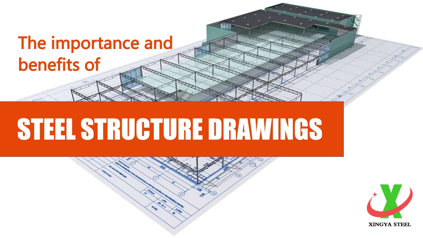
In steel structure engineering, drawings serve as the core technical documents throughout the entire process of design, fabrication, and construction. Their key functions include:
1. Precise Representation of Design Intent
Structural Visualization: Multi-dimensional drawings (plans, elevations, sections) illustrate the layout, component geometry, and spatial relationships.
Technical Specifications: Define material grades (e.g., Q355B steel), cross-sectional dimensions (e.g., H-beam 400×200×8×12), connection methods (e.g., 10.9S bolts or weld symbols), and anti-corrosion requirements (e.g., 80μm hot-dip galvanizing).
Detail Drawings: Highlight complex connections (e.g., beam-column joints, base plates) to ensure clear load transfer paths.
2. Authoritative Basis for Fabrication
Cutting & Machining Guidance: Provide exact dimensions, edge preparations (e.g., 30° V-groove welds), and hole positioning (e.g., CNC cutting requires CAD data).
Process Requirements: Specify weld procedures, bolt-hole tolerances (±0.5mm), camber values (L/500), and other QC criteria.
BOM Generation: Drawings include bills of materials (e.g., bolt quantities, stiffener plate thickness) for procurement and cost estimation.
3. Installation Guidelines
Erection Benchmarks: Indicate control points, elevations (±0.000 to +12.600), and assembly sequences (e.g., columns before bracing).
Field Adaptability Checks: Verify alignment with site conditions (e.g., adjusting anchor bolt deviations via reaming).
Inspection Standards: Reference tolerances (e.g., verticality ≤H/1000, deflection limits L/400) for quality acceptance.
4. Collaboration & Management Tool
Interdisciplinary Coordination: Clash detection with architectural/MEP drawings (e.g., avoiding pipe supports).
Change Tracking: Revisions (e.g., Rev.03) ensure all parties use updated documents.
Legal Validity: Stamped drawings serve as contractual evidence in disputes.
5. Digital Integration
BIM Foundation: Drive 3D modeling (e.g., Tekla) for virtual construction.
Automated Fabrication: DXF files direct CNC machining (cutting/drilling).
Maintenance Data: As-built drawings linked to RFID tags for lifecycle management.
Key Drawing Types & Applications
Industry Standards
Compliant with GB/T 50105-2021 (Chinese drawing standards) or AISC/EN for international projects.
Seismic designs must indicate plastic hinge locations (e.g., RBS connections).
Accurate drawings enable millimeter-level precision in steel construction, ensuring efficient industrialization from design to reality.
Related Posts
Online Message
TOUCH WITH US
